


Rocker Lever Removal and Inspection Procedures
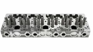
The rocker lever assembly in Cummins ISM, ISMe, and QSM11 engines is a critical component responsible for transferring motion from the camshaft lobes to the valves and injectors . Proper inspection and maintenance of the rocker lever assembly ensures smooth engine operation, accurate valve timing, and optimal fuel injection performance .
This guide provides step-by-step procedures for removing, inspecting, and reassembling rocker levers , including wear checks, lubrication points, and best practices for reinstallation .
For specific torque values, valve lash adjustments, and reassembly specifications , consult an OEM service manual or contact Diesel Pro Power for expert guidance .
Parts Catalog for ISM Cummins Marine and Industrial Engines
Parts Catalog for QSM11 Cummins Marine and Industrial Engines
Safety and Preparation Before Rocker Lever Removal
Before removing the rocker lever assembly , proper safety measures must be followed to prevent damage to engine components and ensure safe handling .
Personal Protective Equipment (PPE)
✔
Safety glasses
– Protects against
debris and pressurized fluids
.
✔
Mechanic gloves
– Prevents
cuts and burns
from engine components.
✔
Steel-toe boots
– Protects against
heavy falling parts
.
✔
Hearing protection
– Recommended when
working in high-noise environments
.
Work Area and Tool Preparation
- Ensure a clean, well-lit workspace to avoid contamination.
- Have all tools and measuring instruments properly calibrated .
- Use magnetic trays or labeled containers
to store fasteners and small components.
Essential Tools for Rocker Lever Service

✔
Torque wrench
– For proper bolt tightening.
✔
Feeler gauges
– For measuring
valve lash clearance
.
✔
Dial indicator
– For checking
wear on rocker lever pivots
.
✔
Straightedge and micrometer
– For checking
rocker arm alignment
.
✔
Solvent and cleaning brushes
– For
degreasing components before inspection
.
Step-by-Step Rocker Lever Removal and Inspection Procedures
The rocker lever assembly must be removed carefully and inspected thoroughly to ensure proper function and longevity .
Step 1: Engine Preparation Before Rocker Lever Removal
- Shut Down the Engine and Allow it to Cool
- Never attempt to remove components from a hot engine
to prevent burns or warping.
- Never attempt to remove components from a hot engine
to prevent burns or warping.
- Disconnect the Battery and Electrical Components
- Prevent accidental engine cranking
by disconnecting the
negative battery cable
.
- Prevent accidental engine cranking
by disconnecting the
negative battery cable
.
- Remove the Valve Cover
- Loosen and remove the valve cover bolts .
- Carefully lift the
valve cover off
and inspect the
gasket for damage
.
Step 2: Removing the Rocker Lever Assembly
- Loosen the Rocker Lever Shaft Bolts Evenly
- Loosen bolts in stages to relieve spring tension gradually.
- Avoid loosening one bolt completely before others
to prevent component misalignment.
- Remove the Rocker Lever Assembly
- Lift the entire rocker lever shaft assembly carefully to avoid damaging the valve bridge .
- Place the
rocker assembly on a clean workbench
for inspection.
- Inspect Pushrods and Rocker Lever Contact Points
- Remove pushrods one by one , ensuring they remain in order for reinstallation.
- Inspect the tips for excessive wear or bending
.
Step 3: Rocker Lever Visual Inspection
- Inspect Rocker Lever Pivot Points
- Check for excessive wear, scoring, or looseness in pivot bores .
- If wear exceeds
OEM-specified tolerances
, the rocker lever must be
replaced
.
- Examine the Valve Contact Surfaces
- Look for
pitting, uneven wear, or cracks
where the rocker lever contacts the
valve stem
.
- Look for
pitting, uneven wear, or cracks
where the rocker lever contacts the
valve stem
.
- Check the Adjusting Screws and Lock Nuts
- Ensure threads are undamaged and adjuster screws turn freely .
- Replace
worn or damaged adjuster screws
.
- Measure Rocker Lever Bushing Clearance
- Use a micrometer to measure the clearance between the bushing and shaft .
- If clearance
exceeds specifications
, replace the
rocker lever bushing
.
Step 4: Checking Rocker Lever Shaft and Oil Supply
- Inspect the Rocker Lever Shaft for Wear
- Roll the shaft on a flat surface and check for bends or misalignment .
- Measure
shaft diameter at multiple points
to detect
wear or tapering
.
- Ensure Proper Oil Passage Flow
- Blow compressed air through the shaft oil passages to remove blockages.
- If passages are clogged,
clean with solvent
before reinstalling.
Step 5: Checking Rocker Lever Alignment and Straightness
- Use a Straightedge to Check Rocker Alignment
- Place a straightedge along the rocker lever shaft to check for misalignment .
- If the rockers
do not sit evenly
, replace
damaged components
.
- Measure Valve Stem Contact Location
- Use a dial indicator to check rocker lever movement .
- Verify
contact points align with valve stems properly
.
Step-by-Step Rocker Lever Reinstallation
After completing inspections and necessary repairs , the rocker lever assembly must be reinstalled correctly to ensure proper valve operation .
Step 1: Preparing the Rocker Lever Assembly for Installation
- Lubricate All Moving Parts
- Apply engine assembly lubricant to the rocker shaft bushings, pivot points, and adjuster screws .
- Ensure
oil passages are clean
before installation.
- Reinstall the Rocker Lever Assembly
- Carefully position the rocker assembly over the pushrods and valves .
- Align the
rocker lever shaft with the mounting holes
.
- Install and Torque the Rocker Lever Shaft Bolts
- Tighten bolts gradually and evenly in a crisscross pattern .
- Follow the
OEM torque specifications
for final tightening.
Step 2: Adjusting Valve Lash Clearance
Proper valve lash adjustment ensures optimal valve timing and fuel injector operation .
- Rotate the Engine to Top Dead Center (TDC)
- Turn the
crankshaft until cylinder 1 is at TDC on the compression stroke
.
- Turn the
crankshaft until cylinder 1 is at TDC on the compression stroke
.
- Use Feeler Gauges to Measure Valve Clearance
- Insert a feeler gauge between the rocker lever and valve stem .
- Adjust the
set screw until the correct clearance is achieved
.
- Torque the Adjusting Screw Lock Nuts
- Secure lock nuts to prevent movement after adjustment.
- Recheck
clearances before final tightening
.
Step 3: Reinstalling the Valve Cover and Final Checks
- Inspect and Replace the Valve Cover Gasket
- If the gasket
shows signs of wear or damage
, install a
new gasket
.
- If the gasket
shows signs of wear or damage
, install a
new gasket
.
- Secure the Valve Cover and Bolts
- Tighten the
valve cover bolts evenly
to prevent leaks.
- Tighten the
valve cover bolts evenly
to prevent leaks.
- Reconnect the Battery and Start the Engine
- Listen for abnormal noises or ticking sounds indicating improper adjustments.
- Check
oil pressure and valve movement
for proper operation.
Final Notes on Rocker Lever Inspection for Cummins ISM, ISMe, and QSM11
✔
Always follow the correct torque sequence when tightening rocker lever bolts.
✔
Keep components clean and lubricated during reassembly to prevent wear.
✔
Inspect pushrods and valve stems for proper alignment before final assembly.
✔
Recheck valve lash adjustments after the first few hours of engine operation.
✔
Consult an OEM manual or Diesel Pro Power for expert guidance.
By following these best practices for rocker lever removal, inspection, and reinstallation , you ensure smooth engine operation, optimal valve timing, and extended service life for Cummins ISM, ISMe, and QSM11 engines .
Parts Catalog for ISM Cummins Marine and Industrial Engines
Parts Catalog for QSM Cummins Marine and Industrial Engines